Brushless motor dry goods, an article to take you to understand its control principle
 May 11, 2021|
 View:744
The most complete brushless motor dry goods, an article to take you to understand its control principle
What are the technologies in the brushless motor, how to explain those terms, and what are the differences and connections between various parameters and equipment?
Basic concepts of brushless motor
According to the structure and working principle of the motor, we can divide the motor into brushless motor, inner rotor brushless motor and outer rotor brushless motor.
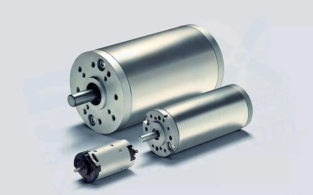
Brush motor: also known as DC motor or carbon brush motor, it is the oldest motor type and the most numerous motor type by far. When the motor is working, the coil and commutator rotate, while the magnetic steel and carbon brush do not rotate. The alternating change of the direction of the coil current is completed by the commutator and brush rotating of the motor. This kind of motor has the advantages of relatively low cost, high torque, simple structure and easy maintenance. However, due to structural limitations, so the shortcomings are also relatively obvious: 1, mechanical commutator sparks caused by the friction of the commutator and the brush, electromagnetic interference, noise, short life; 2, complex structure, poor reliability, many failures, the need for frequent maintenance; 3. Due to the existence of commutator, the further decrease of rotor inertia is restricted, which affects the dynamic performance. So in the mold field is mainly used in the slow speed and insensitive to vibration of the car model, ship model above, rarely use a brush motor.
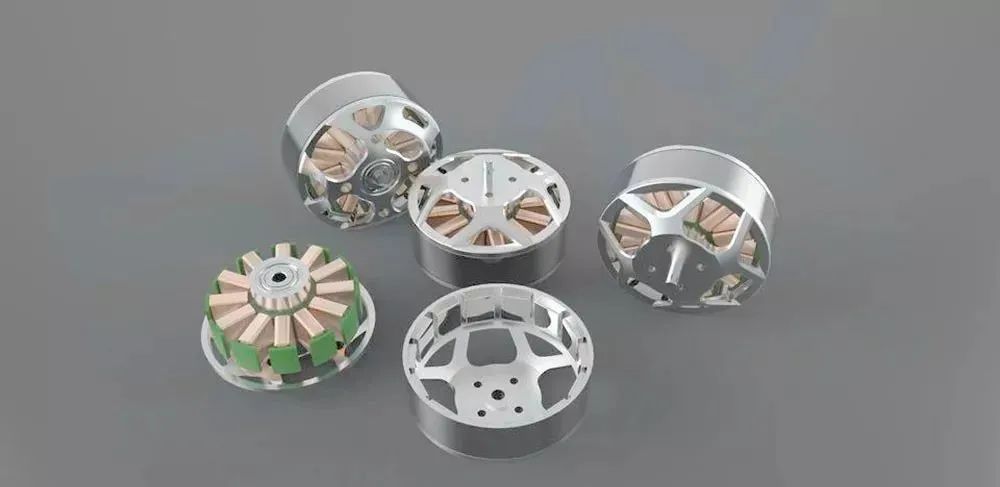
Brushless motor: this is a brush motor mould industry, in addition to outside to use most of a motor, brushless dc motor without the use of mechanical brush device, using square wave self-control type permanent magnet synchronous motor, with hall sensor to replace carbon brush and commutator rotor in ndfeb permanent magnet materials, the performance has a great advantage compared with the general traditional dc motor. With high efficiency, low energy consumption, low noise, long life, high reliability, servo control, stepless frequency conversion speed regulation and other advantages, as for the disadvantage...... Is more expensive than the brush, not good maintenance, widely used in model aircraft, high-speed car model and ship model.
However, a single brushless motor is not a complete power system, brushless basically must be controlled by the brushless controller, that is, electric adjustment to achieve continuous operation. Ordinary carbon brush motors rotate windings, while brushless motors rotate magnets regardless of their external or internal rotor structures. So any motor is composed of a stator and a rotor.
The stator of the brushless motor is the part that generates the rotating magnetic field and can support the rotor to rotate. It is mainly composed of silicon steel sheet, enameled wire, bearing and supporting parts. The rotor is a part that is rotated by the action of the stator rotating magnetic field, which is composed of a rotating shaft, a magnet and a supporting part. In addition, the pole logarithm of stator and rotor also affects the speed and torque of the motor.
The structure of brushless motor
The front cover, middle shell and back cover of the brushless motor are mainly integral structural parts, which play the role of building the overall structure of the motor. But the outer rotor brushless motor shell is also the magnetic circuit path of the magnet, so the shell must be composed of magnetic conductive material. The housing of the inner rotor is only a structural part, so the material is not limited. However, the inner rotor motor has a rotor core more than the outer rotor motor, and the role of the rotor core is also to play the role of magnetic path.
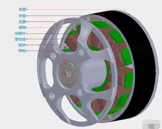
Magnet: is installed on the rotor, is an important part of the brushless motor, brushless motor most of the performance parameters are related to the magnet, including power, speed, torque and so on.
Silicon steel sheet: is an important part of a slotted brushless motor, of course, no slotted brushless motor is no silicon steel sheet, but at present the vast majority of brushless motor are slotted. Its main function in the whole system is to reduce the reluctance and participate in the magnetic circuit operation.
Rotating shaft: it is the direct force part of the motor rotor, the hardness of the rotating shaft must be able to meet the requirements of high-speed rotation of the rotor.
Bearings: it is the guarantee of smooth motor operation. Bearings can be divided into sliding bearings and rolling bearings, and rolling bearings can be subdivided into ten categories such as deep groove ball bearings, needle rolling bearings and angular contact bearings. At present, most brushless motors are using deep groove ball bearings.
The working principle of brushless DC motor
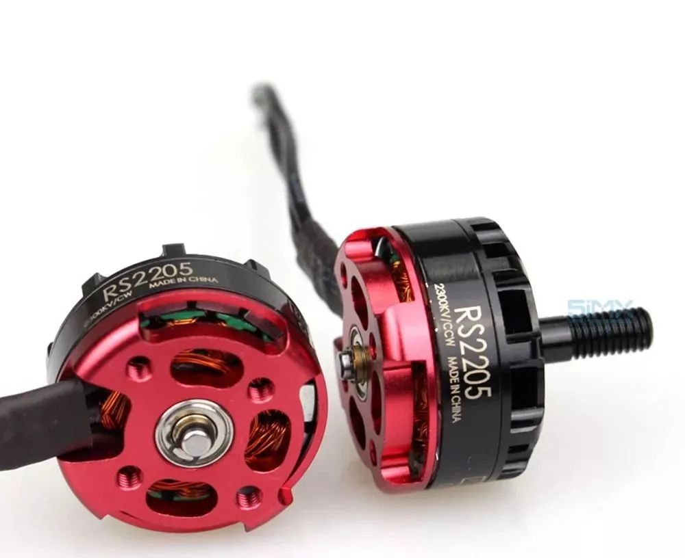
The brushless DC motor power system is composed of rotor, stator and position sensor. Position sensing according to the change of rotor position, along a certain sequence of stator winding current converter (i.e. detecting the rotor magnetic pole relative to the position of the stator winding, and in determining the location of position sensor signal, the signal conversion circuit to control the power switch circuit, after processing according to certain logic relation between winding current switch). The operating voltage of the stator windings is provided by an electronic switching circuit controlled by the position sensor output.
Position sensor has magnetic sensitive type, photoelectric type and electromagnetic type three types
A brushless DC motor with a magnetosensitive position sensor, whose magnetosensitive sensor parts (such as Hall element, magnetosensitive diode, magnetosensitive electrode tube, magnetosensitive resistor or special purpose integrated circuit, etc.) are mounted on the stator assembly to detect the magnetic field changes caused by the rotation of permanent magnet and rotor.
The brushless DC motor adopts photoelectric position sensor, the photoelectric sensor is arranged on the stator assembly according to a certain position, the light shield is installed on the rotor, and the light source is light-emitting diode or small bulb. When the rotor rotates, due to the role of the shade plate, the photosensitive components on the stator will generate pulse signals intermittently at a certain frequency.
Using electromagnetic position sensor brushless dc motor, is in the electromagnetic sensors are installed on the stator component parts (such as the coupling transformer, close to switch, LC resonance circuit, etc.), when the permanent magnet rotor position changes, electromagnetic effect will make the electromagnetic sensor produces high frequency modulation signal (the amplitude changes with the rotor position).
Simply put, the brushless DC motor is to rely on changing the frequency and waveform of the alternating current wave input to the stator coil of the brushless motor to form a magnetic field around the winding coil that rotates around the geometric axis of the motor. This magnetic field drives the permanent magnet magnetic steel on the rotor to rotate, and the motor starts to rotate. The performance of the motor and the number of magnetic steel, magnetic steel, magnetic flux intensity factors such as input voltage, the motor size, more with brushless motor control performance has much to do, because the input is the direct current, current need electronic governor turned it into three phase alternating current (ac), also need to receive control signal from the remote control receiver, control motor speed, to meet the needs of the model using.
In general, the structure of the brushless motor is relatively simple, really determine its performance or brushless electronic governor (i.e., electricity), good electrical tuning needs a single chip microcomputer control program design, circuit design, control the overall process, such as complex processing technology, so the prices are much higher than the brushless motor in general.
Let me first review some basic rules: the left-hand rule, the right-hand rule, and the right-hand spiral rule. Don't be overwhelmed. I'll explain it to you.
The left hand rule, and this is the basis of the force analysis of the motor rotation, is simply that the current carrying conductors in the magnetic field, will be subjected to the force.
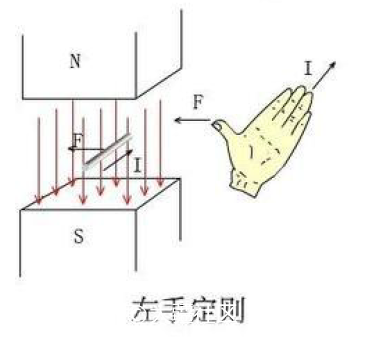
Let the magnetic induction line pass through the front of the palm, the direction of the finger is the direction of the current, and the direction of the thumb is the direction of the magnetic force. I believe that people who like to play models have a certain physical basis.
The right hand rule, which is the basis for induced electromotive force, in contrast to the left hand rule, conductors in a magnetic field are pulled by a force to produce an electromotive force by cutting magnetically sensitive lines.
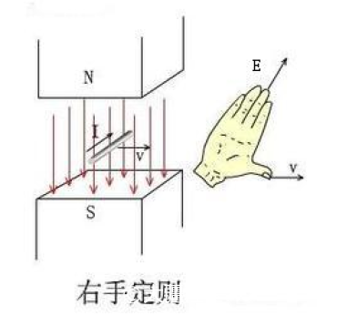
Let the magnetic induction line pass through the palm, the thumb direction is the direction of motion, the finger direction is the direction of electromotive force generated. Why do we talk about induced electromotive force? Don't know if you have similar experiences, the motor of the three phase line together, with the hand to turn the electricity opportunities found resistance is very big, this is because in the process of rotational motor produces the induced electromotive force, so as to generate an electric current, current flows through the conductor in magnetic field and will produce the force and rotation in the opposite direction, you will feel the rotation has a lot of resistance. Do not believe can try.
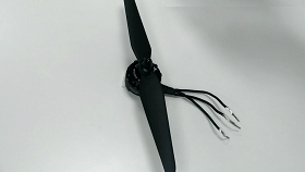
The three-phase wire is separated and the motor can turn easily
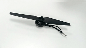
Combined three-phase line, motor rotation resistance is very large
The right hand screw rule: hold the solenoid with the right hand and bend the four fingers in the same direction as the current. Then the end pointed by the thumb is the n-pole of the solenoid.
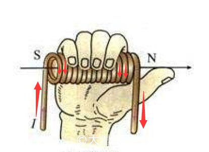
This rule is the basis for the polarity judgment of the energized coil, and the direction of the red arrow is the direction of the current.
Having looked at the three rules, let's first look at the basic principle of motor rotation.
Part I: DC motor model
We found a high school physics of the DC motor model, through the magnetic loop analysis for a simple analysis.
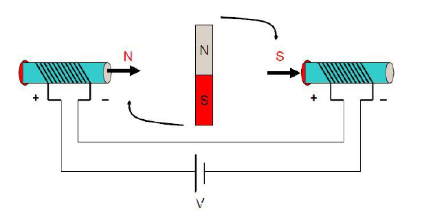
State 1
When both ends of the coil when applying a current, according to the right hand screw rule, produces the direction pointing to the right and magnetic induction intensity B (as shown in the thick direction of arrow), and in the middle of the rotor will try to make its own internal magnetic induction line direction consistent with the direction of magnetic induction line, to form a closed magnetic field lines shortest circuit, so that the rotor will be rotated clockwise.
When the direction of the rotor magnetic field is perpendicular to the external magnetic field, the rotor is subjected to the maximum rotational torque. Notice that it says the moment is greatest, not the force is greatest. It is true that the rotor has the greatest magnetic force when its magnetic field is aligned with the external field, but when the rotor is horizontal and its moment arm is zero, it will not rotate. By the way, torque is the product of a force and a moment arm. If one of them is zero, the product is zero.
When the rotor is turned to the horizontal position, it will continue to rotate clockwise due to inertia, although it is no longer affected by the rotation moment. In this case, if the current direction of the two solenoids is changed, as shown in the figure below, the rotor will continue to rotate clockwise forward
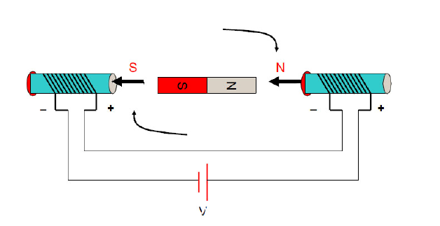
State 2
By constantly changing the direction of current on both ends of the solenoid, the inner rotor will continue to rotate. The act of changing the direction of the current is called commutation. A footnote: the timing of commutation is only related to the position of the rotor and is not directly related to any other quantity.
The second part: three - phase two - pole internal rotor motor
Generally speaking, the three-phase winding of the stator has a star connection mode and a triangle connection mode, and the "two-two conduction mode of three-phase star connection" is the most commonly used, and this model is used here to do a simple analysis.
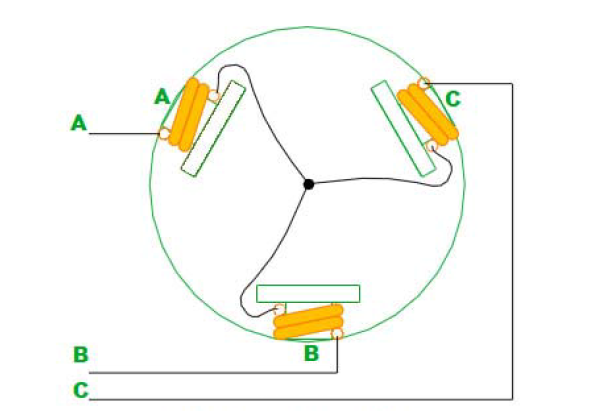
The figure above shows how the stator windings are connected (the rotor is not drawn as if it is a dipole magnet). The three windings are connected together in a "Y" shape through a central connection point. The whole motor leads out three lines A,B and C. So when they're charged in pairs, there are 6 cases, AB, AC, BC, BA, CA,CB and notice that this is in order.
Now let me look at the first stage: electricity is connected to AB
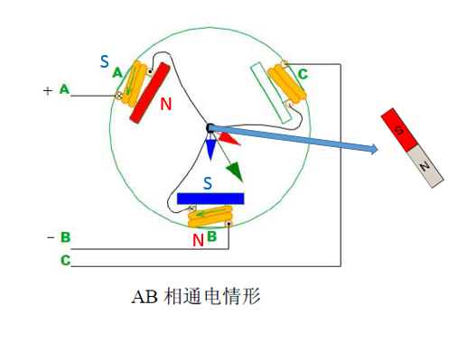
When AB is connected with electricity, the direction of magnetic induction line generated by pole A coil is shown by the red arrow, and the direction of magnetic induction line generated by pole B is shown by the blue arrow. Then the direction of resultant force is shown by the green arrow. Then suppose there is A dipole magnet. According to "the rotor in the middle will try to keep the direction of its internal magnetic induction line consistent with the direction of the external magnetic induction line", the direction of N pole will coincide with the direction shown by the green arrow. As for C, he has nothing to do with it for the time being.
Stage 2: AC connected power
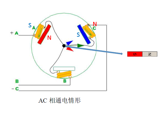
The third stage: BC connected electricity
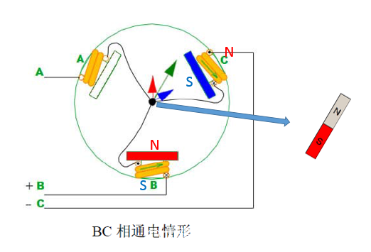
The third stage: BA communicates electricity
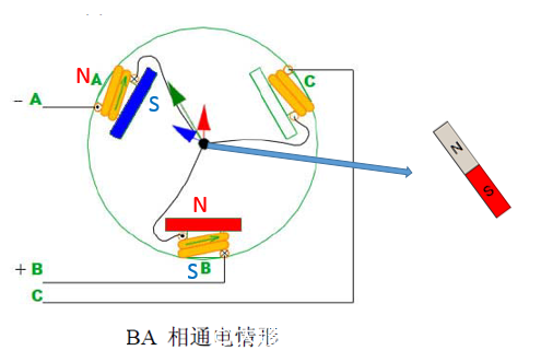
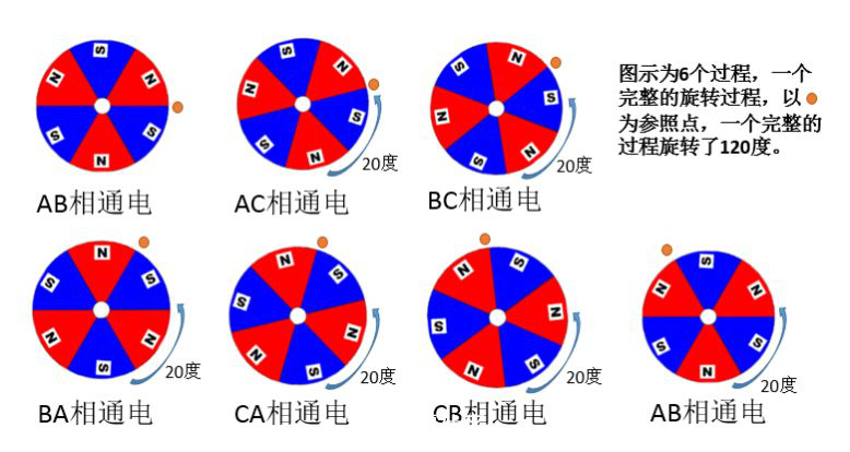
In order to save space, we will not describe the CA\CB model, you can do your own analogy. The following is the state diagram of the intermediate magnet (rotor) :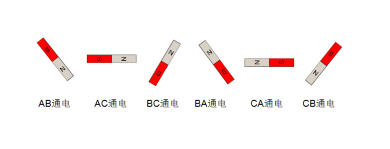
The rotor rotates 60 degrees for each process
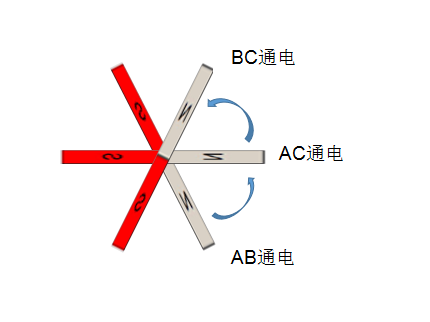
Six processes complete the rotation, including six commutations.
The third part: three - phase multi - winding multi - pole internal rotor motor
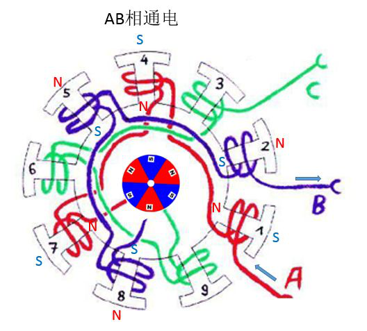
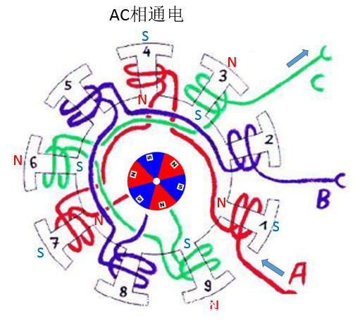
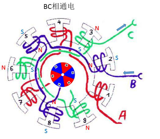
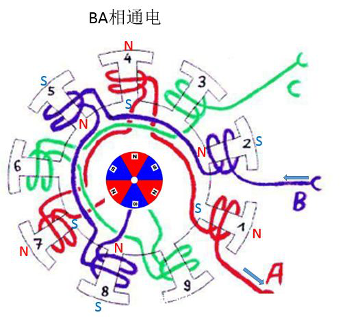
Let's take a more complicated picture. Figure (a) shows a three-phase nine-winding six-pole (three-pole pair) internal rotor motor, whose winding wiring is shown in Figure (b). As can be seen from Figure (b), the three-phase winding is also connected together at the intermediate point, which also belongs to the star connection mode. In general, the number of windings of the motor is not the same as the number of permanent magnet poles (for example, the number of permanent magnet poles is 9 winding 6, instead of 6 winding 6), in order to prevent the stator teeth from being aligned with the rotor's magnetic steel.
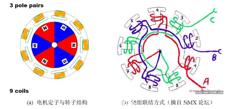
The principle of its movement is: the rotor N pole and the electrified winding S pole has the alignment movement trend, and the rotor S pole and the electrified winding N pole has the alignment movement trend.
So S and N attract each other, and notice that there's a little bit of a difference.
Well, let me break it down for you again.
Stage 1: Electric connection for AB
Stage 2: AC connected power
The third stage: BC connected electricity
Stage 4: Power on BA
Stage 5: CA energized
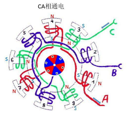
Stage 6: CB energized
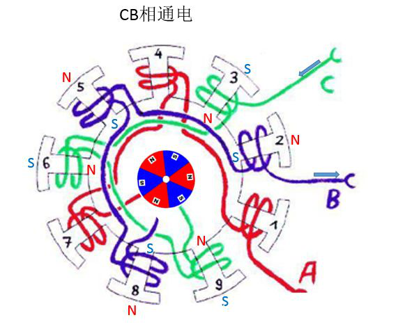
The above are six different electrification states, of which five rotational processes have been experienced. Each process is 20 degrees.
Part IV: Brushless DC motor with outer rotor
Having looked at the structure of the inner rotor brushless DC motor, let's look at the outer rotor. The difference is that the outer rotor motor will be in the center of the original magnetic steel into pieces, affixed to the shell, motor running, is the whole shell in the rotation, and the middle of the stator coil does not move. The outer rotor brushless DC motor is better than the inner rotor. The moment of inertia of the rotor is much larger (because the main mass of the rotor is concentrated on the shell), so the speed is slower than that of the inner rotor motor, and the KV value is usually between several hundred and several thousand. It is also the main brushless motor used in model aircraft.
By the way. KV value of brushless motor is defined as: speed /V, which means the speed value of the increase of idle speed of the brushless motor when the input voltage increases by 1 volt. For example, the maximum no-load speed of an external rotor brushless motor with a nominal value of 1000kV at 11 volts is 11000rpm (RPM stands for revolutions per minute).
The same series brushless motors with the same size will show different KV characteristics according to the number of winding turns. The number of winding turns is more, the KV value is low, the maximum output current is small, and the torque is large; The number of winding turns is less, the KV value is high, the maximum output current is large, and the torque is small. I have previously tested the limit current of 2204 motor of the crossover machine. A single motor can load 25A, while 2212 series motors can not load 15A.
Structure of outer rotor brushless DC motor:

Analysis method and the inner rotor motor similar, we can analyze and judge according to the law of right hand spiral coil N/S pole and N pole of permanent magnet rotor and the stator winding of the S pole has a tendency to alignment (attract), permanent magnet rotor S pole and N pole of the stator winding is aligned (attract), so as to drive motor rotation.
Structure analysis of 22121000kV brushless motor.
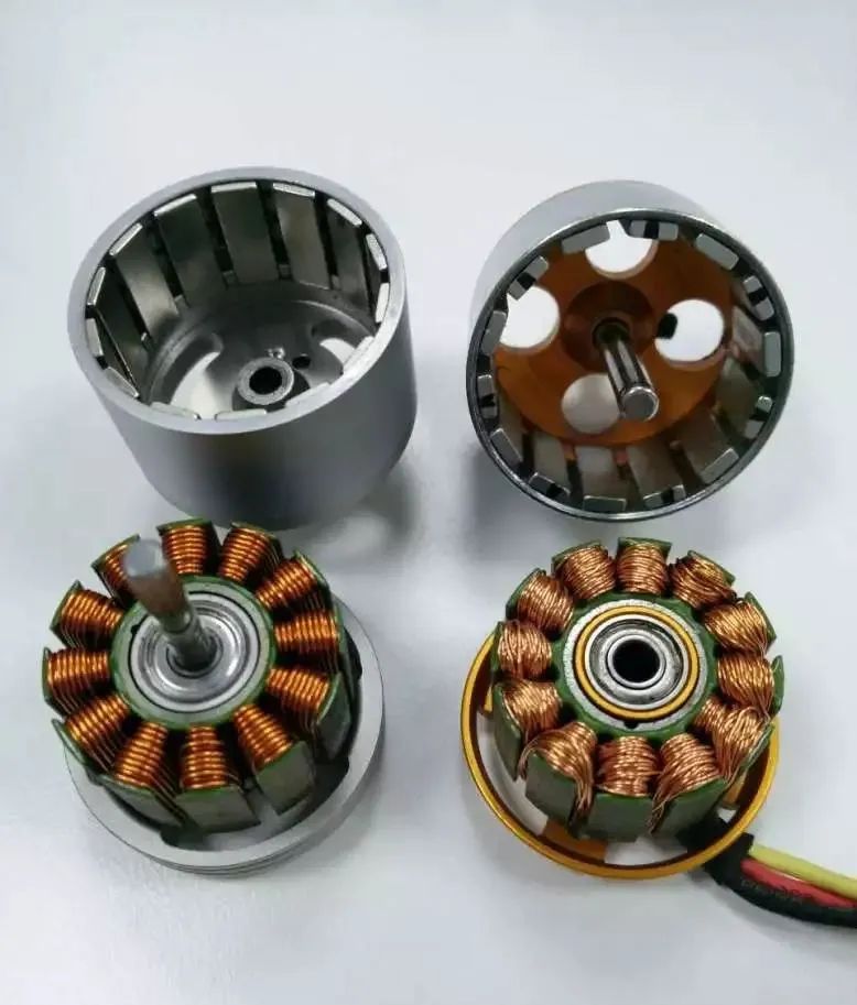
Picture DJI2312S motor and XXD2212 motor (anatomical diagram)
The structure is as follows: the stator windings are fixed on the base, the rotating shaft and the housing are fixed together to form a rotor, which is inserted into the bearing in the middle of the stator.
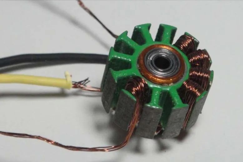
The picture is the disassembly of XXD2212 coil
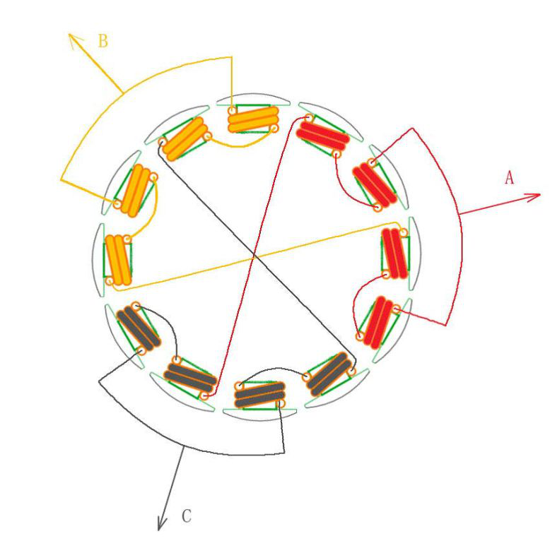
The picture shows 12 winding 14 poles (i.e. 7 pairs of poles), motor winding diagram.
It can be seen that, although the number of windings and magnetic poles can vary in many ways, the power-on order is actually the same from the perspective of electric regulation control. That is to say, no matter the outer rotor or the inner rotor motor, the power-on and phase-switching sequence follows AB->AC->BC->BA->CA->CB.
Of course, if you want to turn the motor upside down, the electronic way is to turn it upside down; The physical method is to just switch any two lines, so if you switch A and B, then the order is ba-> bc-> ac-> ab-> cb-> CA, and you notice that the order is completely reversed here.
AB interlinked electric
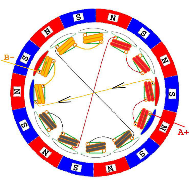
AB interlinked electric
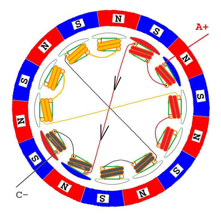
BC connected electricity
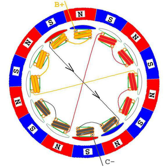
BA is same
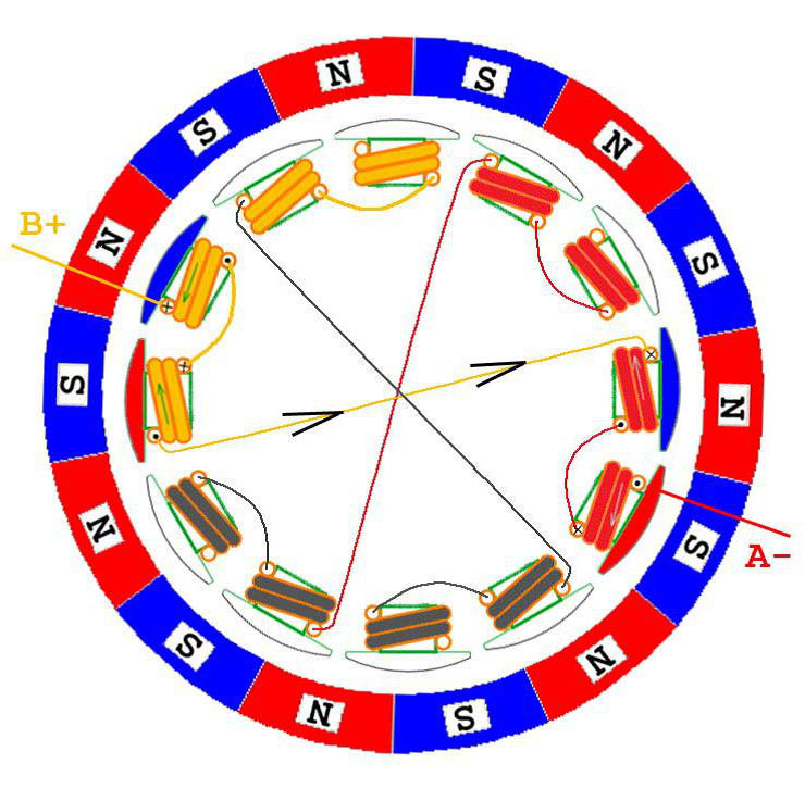
CA is same
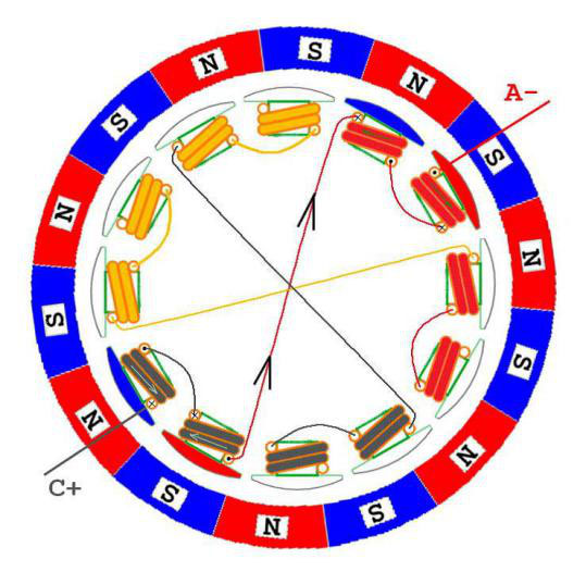
CB interlinked electric
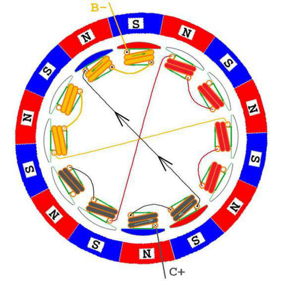
It should be noted that because each lead wire is connected to two windings at the same time, the current is divided in two ways. In order to simplify the problem as much as possible, only the current direction of the main road is drawn in the following figures, and the current direction of the other road is not drawn. The specific situation of the other road is analyzed later, which involves the commutation position of circuit detection.
A term used in brushless motors
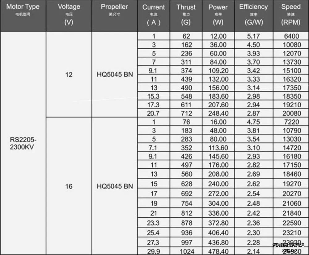
Rated voltage: that is, the brushless motor suitable for the working voltage, in fact, brushless motor suitable for the working voltage is very wide, the rated voltage is specified load conditions and the situation. For example, the 2212-850kV motor specifies the load of the 1045 propeller and its rated operating voltage is 11V. If the load is reduced, such as with a 7040 propeller, the motor can work at 22V. However, this operating voltage is not infinitely rising, mainly controlled by the electronic controller to support the maximum frequency. So the rating is determined by the working environment.
KV value: Brushless DC motor is based on the rated working voltage to label the rated speed, brushless motor introduced the concept of KV value, and let the user can intuitively know the specific speed of the brushless motor under the specific working voltage. Actual speed is equal to the value of KV times the working voltage, that's what KV really means, it's the speed per minute at 1V. The speed of the brushless DC motor is proportional to the voltage, and the speed of the motor will increase linearly with the voltage rise. For example, the speed of 2212-850kV motor at 10V voltage is: 850*10=8500RPM(RPM, speed per minute).
Torque :(Torque, Torque) The driving torque generated by the rotor in a motor that can be used to drive a mechanical load. We can understand the force of the motor.
Speed: The speed of the motor per minute, generally expressed in RPM.
Maximum current: Maximum current that the motor can withstand and operate safely
Maximum power: the maximum power that the motor can withstand and work safely = voltage * current
Brushless motor power and efficiency
We can simply understand that the motor output power = speed * torque, in the same power, torque and speed is a reciprocal relationship, that is, the higher the speed of the same motor, the lower the torque, and the opposite is still the same. It is impossible to require a motor to have a higher speed and a higher torque, and this rule applies to all motors. For example: 2212-850KV motor, in the case of 11V can drive 1045 paddle, if the voltage is doubled, its speed is also doubled, if the load is still 1045 paddle, the motor will soon be burned because of the sharp rise in current and temperature.
Each motor has its own upper limit of power, the maximum power is this upper limit, if the working conditions exceed this maximum power, will cause the motor to burn down at high temperature. Of course, this maximum power is also obtained when the operating voltage is specified. If the operating voltage is higher, the reasonable maximum power will also be increased. This is because: Q=I2R, the conductor's heat is proportional to the square of the current, at a higher voltage, if it is the same power, the current will drop, resulting in the reduction of heat, making the maximum power increase. This also explains why 22.2V or even 30V batteries are widely used to drive multi-axis aircraft in professional aerial photography aircraft. The brushless motor under high pressure has low current, low heat and higher efficiency.
People often ask: what is the difference between 2208 1000KV and 2216 1000KV? They are both 1000KV, aren't they all the same? Well, that's a big difference.
In the case of the motor diameter, KV value are the same, the higher the motor natural power is greater, the greater the power of the motor natural can drive the greater the load. Like a man 100 catties, a man 160 catties, you ask them to carry a bag of 50 catties of rice, 100 catties of men although said a little bit difficult but also can carry, 160 catties of men think it is a small dish. But what if they had to carry two bags of rice? 160 catties of the man clenched his teeth also back up, 100 catties of the man is afraid the waist is not straight up, this is their difference. For the motor, the easier the work, the higher the efficiency, using the previous theory is, iron consumption is low copper consumption is low.
Remember the formula: torque is proportional to the square of the current
As the motor works more and more tired, its efficiency will rapidly decrease. Therefore, when selecting the multi-shaft motor, it is necessary to choose the appropriate power motor and the propeller matched with it, so that the motor can work in a relatively easy state. Generally speaking, it is better to work between 30-45% of the maximum power when hovering. A young ox shall not draw a cart, nor a great ox a cart.
The relationship between voltage and efficiency of brushless motor
Let's start with two formulas:
1, power = voltage * current
2, heat = the square of the current * resistance
Two conclusions are drawn from the formula: under the same power, the higher the voltage, the smaller the current, and it is deduced: under the same power, the higher the voltage, the smaller the heat. The conclusion is: the same aircraft, the higher the voltage used, the lower the current and the less heat, the higher the efficiency.
Now you can see why the high voltage wire should be connected to the high voltage of 100kV, even 220kV, 550kV (this KV is kilovolts).
Of course, the aircraft is powered by batteries, to be precise, lithium batteries. The number of pieces of lithium batteries naturally depends on the size of the battery. The larger the battery, the higher the voltage it can operate. So in terms of voltage, in fact, we can do not much, because a lot of batteries in the market are serialized, such as 450 such models, you can go to find 450 helicopter 6S battery, but the price is very high, and the electricity adjustment price is also higher. So in terms of voltage, what we should do is to avoid the use of low-voltage batteries for large models as far as possible, which will cause a relatively high working current and thus greater copper consumption. Also, avoid using high-voltage batteries on small planes, which can be too heavy.
The pole logarithm of a brushless motor
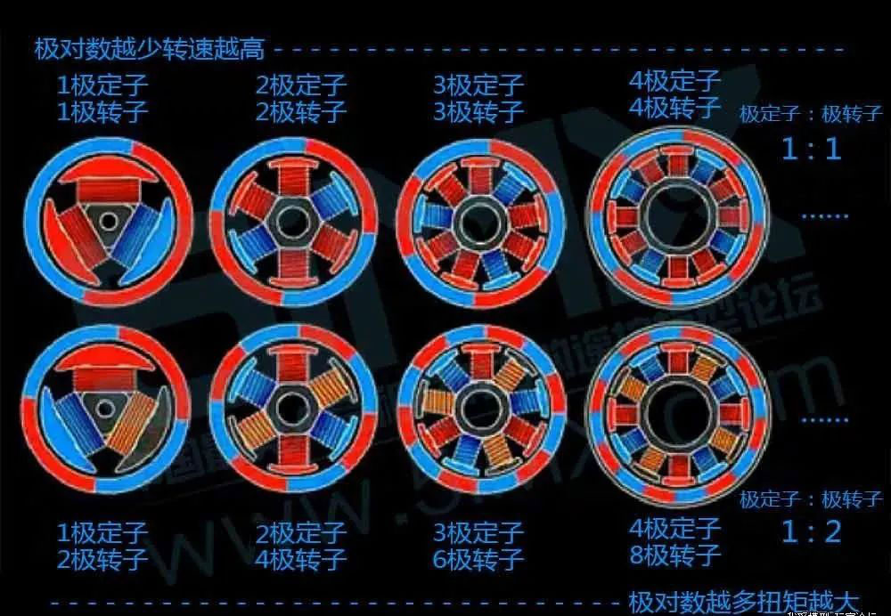
The rotation speed of the magnetic field, also known as synchronous speed, is related to the frequency of the three-phase current and the pole logarithm p. If the stator winding, synthesis of magnetic field at any moment only a pair of poles (pole logarithmic p = 1), the only two magnetic poles, for only a pair of poles of a rotating magnetic field, three phase current change week, synthesis of magnetic field is rotating a week, if is 50 hz alternating current (ac), a rotating magnetic field of the synchronous speed is 50 r/s or 3000 revolutions per minute, in the engineering technology, RPM (r/min) is often used to express the speed. If the magnetic field synthesized by the stator winding has two pairs of magnetic poles (logarithm of magnetic poles P =2), that is, there are four magnetic poles, it can be proved that when the current changes for one period, the synthetic magnetic field rotates 180 degrees in space. Thus, it can be generalized that the synchronous speed of magnetic field rotated by P to magnetic poles is n= 60F/P per minute.
When the pole logarithm is certain, if you change the frequency of the alternating current, you can change the synchronous speed of the rotating magnetic field, which is the basic principle of frequency conversion speed regulation. Since the poles of a motor come in pairs, the polar logarithm is also commonly used.
Magnets for brushless motors
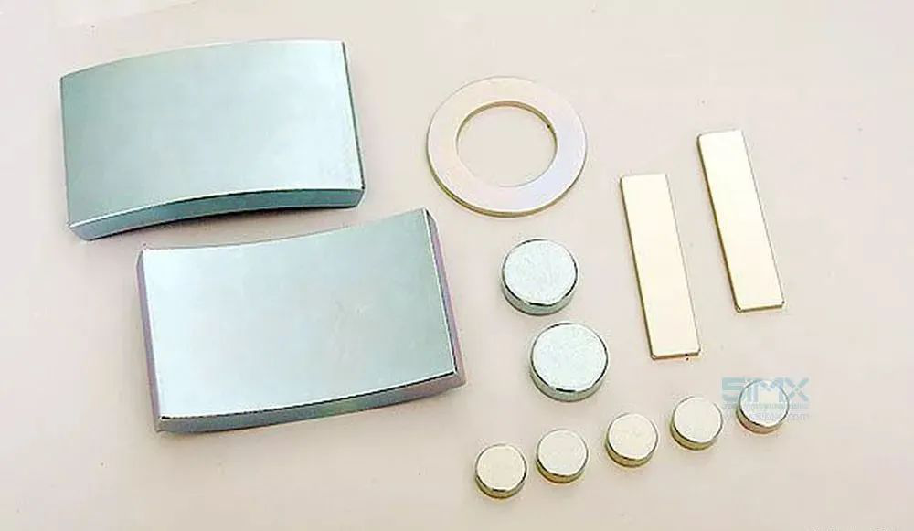
Mold industry brushless motor almost 100% with the "King of Magneto" - NdFeB magnet, the king of Magneto to describe NdFeB magnet is worthy of it, NdFeB magnet is common in our life black ferrite magnet magnetic 3 times! Of course, the price is more than 10 times that of ferrite magnets. After all, the brushless motor belongs to the permanent magnet motor, and the power and characteristics of the permanent magnet motor completely depend on the magnet. Basically, the size and brand of the magnet determine the maximum power of the motor.
There are also differences in the shape of magnets. If you take apart some cheap motors you will find that most magnets are shaped like squares. Square piece shaped magnet processing is simple, the price is relatively cheap, naturally became the choice of the pursuit of cost motor. And many brands of motor choose arc magnet, arc can ensure that the air gap between the magnet and the silicon steel sheet is always consistent, it seems that the power and efficiency are better than the square magnet. However, in disassembling some of the motors, the so-called bread-shaped magnets were found to fit perfectly into the iron shell, but not at the same distance from the silicon steel sheet as the square magnets. About this kind of magnet, I consulted some people in the industry, they believe that this kind of magnet is better than the arc magnet effect, we do not make a conclusion here.
But there is a case of square magnet is also possible, in the multi-slot multi-pole brushless motor (such as 36 slot 42 pole motor), the basic is the use of square magnet, this is because the diameter of the iron shell is large, the square magnet can also be very good and iron shell bonding, and the air gap with the silicon steel sheet is also very uniform.
About brushless motor silicon steel sheet
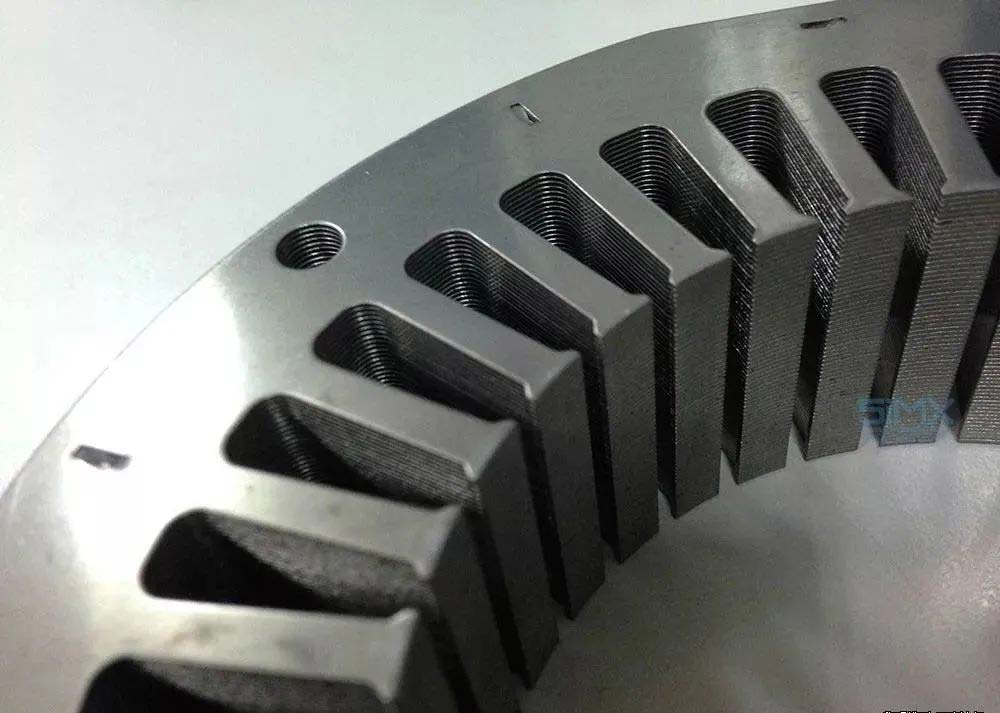
In fact, when junior high school read electromagnetism, I often think of the problem is, why does the motor need silicon steel sheet? Doesn't it mean that an electrified conductor can act in a magnetic field? So why the need for silicon steel sheets? Then I thought for a long time and finally came to a conclusion, that is to do the design of the people will not be more stupid than you!
Air is weak magnetic conductivity, but iron is magnetic conductivity, the role of the silicon steel sheet is to guide the magnetic circuit of the magnet and form a circuit, which requires the motor reluctance (we equate it to understand as resistance) is relatively small. But as you can see, why is it that the stator has all these pieces on it?
Do you know the principle of induction cooker? Why does iron pot put on induction cooker above can be calorific? In fact, this is because ----- similar to iron materials in the rapidly changing electromagnetic field (we think of alternating current, the electricity is instantaneous flying, unlike direct current is always positive to negative) will produce eddy current loss and heat, and the higher the frequency is the greater the heat. The silicon steel sheet is in the rotating magnetic field of the motor, which is the same problem as the iron pot on the induction cooker. The solution is to add silicon to the steel and make it into a thin sheet. Theoretically, the thinner the silicon steel sheet, the less eddy current loss it will produce.
So do you understand the reason why ordinary fixed-wing motors are mostly thick 0.35mm silicon steel sheets, while helicopters and bypass electromechanical machines are mostly 0.2mm silicon steel sheets? The faster the motor speeds, the faster the magnetic field changes, and the greater the eddy current losses. Now most of the multi-axis motor use 0.2mm single silicon steel sheet, so that the motor iron consumption will be much lower.
Related little knowledge: why the high KV motor in the full throttle idling condition will be very hot?
The answer is: it's not the copper wire that's generating the heat, because the current is very small. It is the eddy current loss and hysteresis loss that generate heat, because at this time the motor is completely empty, the speed is relatively high, the eddy current loss is large, and all the losses become heat.
About brushless motor use and maintenance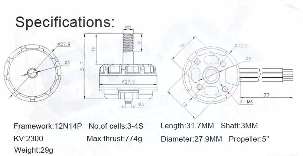
The brushless DC motor is composed of the motor body and the driver. It is a typical mechatronics product and has been widely used in many fields. Users in the use of brushless DC motor when there are some problems also need to pay attention to, then the specific use of brushless DC motor should pay attention to what?
(1) Before disassembly, use compressed air to blow the dust on the surface of the motor, and wipe the surface dirt clean.
(2) Select the working place where the motor is disintegrated and clean up the site environment.
(3) Familiar with motor structure characteristics and maintenance technical requirements.
(4) Prepare tools (including special tools) and equipment needed for disintegration.
(5) In order to further understand the defects in the operation of the motor, a check test can be done before disassembly if conditions permit. To this end, the motor with load test, detailed inspection of the temperature, sound, vibration and other parts of the motor, and test the voltage, current, speed, and so on, and then disconnected the load, a separate no-load inspection test, measuring the no-load current and no-load loss, make a good record.
(6) Cut off the power supply, remove the external wiring of the motor, and make a good record.
(7) Select the appropriate voltage megohmmeter to test the insulation resistance of the motor. In order to compare with the insulation resistance value measured in the last overhaul to judge the change trend and insulation state of the motor insulation, the insulation resistance value measured at different temperatures should be converted to the same temperature, generally converted to 75℃.
(8) Test the absorption ratio K. When the absorption ratio is greater than 1.33, it indicates that the motor insulation has not been affected by moisture or the degree of moisture is not serious. In order to compare with previous data, the absorption ratio measured at any temperature is also converted to the same temperature.
Source:
Blog. SINA "To date the most complete brushless motor work and control principles shared by the author: Shaoshuai -Z
5 IMX "The Old Driver Show You a Comprehensive Understanding of Brushless Motor"
EMAX Silver Swallow: An article that takes you through the brushless motor
Specification for PCB layout of motor drivers
DC motor drive circuit design objectives
In the design of DC motor drive circuit, the following points are mainly considered:
Function: is the motor one-way or two-way rotation? Do you need speed regulation? For one-way motor drive, as long as a high-power transistor or field effect tube or relay directly drive the motor can be, when the motor needs two-way rotation, can use the H-bridge circuit composed of four power elements or use a double-knife double-throw relay. If you do not need to speed, as long as the use of relays can; But if you need to speed, you can use transistor, field effect tube and other switching components to achieve PWM(Pulse Width Modulation) speed.
Performance: For PWM speed motor drive circuit, there are mainly the following performance indicators:
- Output current and voltage range, which determines how much power the circuit can drive the motor.
- Efficiency, high efficiency means not only saving power, but also reducing the heat of the drive circuit. To improve the efficiency of the circuit, we can start from ensuring the switching working state of the power device and preventing common state conduction (a problem that may occur in H-bridge or push-pull circuit, that is, two power devices conduct at the same time to short-circuit the power supply).
- Impact on the control input. The power circuit should have good signal isolation on its input end to prevent high voltage and large current from entering the main control circuit, which can be isolated with high input impedance or optocoupler.
- Impact on power supply. Common state switching can cause the instantaneous drop of the power supply voltage and cause the pollution of the high frequency power supply. High currents may cause ground potential to fluctuate.
- Reliability. The motor drive circuit should be as safe as possible no matter what control signals and passive loads are applied.
1. Input and level conversion:
The input signal line is introduced by DATA. Pin 1 is the ground line and the rest is the signal line. Note that pin 1 is connected to the ground with a 2K ohms resistor. This resistor provides a path for the signal current to flow back when the drive board and the SCM are powered separately. When the drive board and the microcontroller share a power supply, this resistor can prevent large current flowing into the ground wire of the microcontroller motherboard along the line causing interference. In other words, it is equivalent to separating the ground wire of the driving board from the ground wire of the single-chip microcomputer to achieve "a point of grounding".
The high-speed op amp KF347(or TL084) acts as a comparator, converting the input logic signal into a square wave signal close to the power supply voltage range by comparing it with the 2.7V reference voltage from the indicator lamp and a diode. The input voltage range of the KF347 should not be close to the negative supply voltage, otherwise an error will occur. Therefore, a diode is added at the input end of the op-amp to prevent the voltage range overflow. Two resistors at the input, one to limit the current and one to pull the input to a low level when the input is suspended.
Do not replace the op amp with LM339 or any other comparator with an open output, because the high level output impedance of the open output is above 1000 ohms and the voltage drop is large, and the transistor at the next stage will not be able to shut off
2. Grid driving part:
The circuit composed of the triode, resistor and voltage regulator tube further amplifies the signal, drives the gate of the field effect tube and uses the gate capacitance of the field effect tube itself (about 1000pF) for delay, so as to prevent the simultaneous conduction of the field effect tubes of the upper and lower arms of the H bridge (" common state conduction ") from causing the power short circuit.
When the output of the op-amp is at a low level (about 1V to 2V, which cannot completely reach zero), the triode below is cut off and the field effect tube is switched on. The triode above turns on, the field-effect tube cuts off, and the output is high. When the output end of the op-amp is at a high level (about VCC-(1V to 2V), which cannot fully reach VCC), the triode below is switched on and the field effect tube is cut off. The triode above cuts off, the field effect tube turns on, and the output is low.
The above analysis is static, and the dynamic process of switch conversion is discussed below: the on-resistance of the transistor is far less than 2,000 ohms, so when the transistor is switched from cut-off to on-off, the charge on the gate capacitance of the field effect tube can be released rapidly, and the field effect tube can be cut off quickly. However, it takes some time for the triode to switch from on-on to cutoff time for the MOSFET gate to be charged through a 2000 ohms resistor. Correspondingly, the speed of the field-effect tube to switch from on to off is faster than the speed of the cutoff to switch from off to on. If the switching action of two triodes occurs simultaneously, this circuit can make the FET of the upper and lower arms break first and then open, so as to eliminate the common state conduction phenomenon.
In fact, it takes a certain amount of time for the output voltage of the op-amp to change, and during this time the output voltage of the op-amp is in the middle between positive and negative supply voltages. At this time the two audions at the same time, the field effect tube will be closed at the same time. So the actual circuit is a little bit safer than this ideal.
The 12V regulator diode of the field effect tube gate is used to prevent the field effect tube gate from overvoltage breakdown. The voltage withstand of a typical field effect tube gate is 18V or 20V. Adding a voltage of 24V directly will cause breakdown. Therefore, the regulator diode cannot be replaced with a normal diode, but it can be replaced with a 2000 ohms resistor, which will also give a 12V partial voltage.
3. Output part of field effect tube:
There are diodes in reverse parallel between the source and the drain inside the high-power field effect tube. When connected to the H-bridge, it is equivalent to the four diodes used to eliminate voltage spikes have been connected in parallel at the output end, so there is no external diode. A small capacitor in parallel (between OUT1 and OUT2) at the output end can reduce the peak voltage generated by the motor, but it has the side effect of generating peak current when using PWM, so the capacity should not be too large. This capacitance can be omitted when using a low power motor. If you add this capacitor, be sure to use a high voltage, ordinary ceramic capacitors may have a breakdown short circuit fault.
The output ends are connected in parallel by a resistor and LED, capacitor circuit to indicate the direction of rotation of the motor.
4. Performance indicators:
Power supply voltage 15~30 V, the maximum continuous output current 5A/ each motor, a short time (10 seconds) can reach 10A,PWM frequency can be used up to 30KHz(generally 1 to 10KHz). The circuit board contains 4 logically independent power amplifier units, whose output ends are pair-to-pair-to-H bridge, which can be directly controlled by SCM. Realize the motor's bidirectional rotation and speed regulation.
5.PCB layout and wiring:
The high current line should be short and thick as far as possible, and try to avoid passing through the hole. If you must pass through the hole, make the hole bigger (>1mm) and make a small circle of the hole on the solder pad, and fill it with solder when welding, otherwise it may be burned out. In addition, if the regulator tube is used, the wire of the field effect tube source to the power supply and the ground should be as short and thick as possible, otherwise in large current, the voltage drop on this section of the wire may be burned through the positive bias regulator tube and the conduction of the transistor. In the original design, a 0.15 ohms resistor was inserted between the source of the NMOS tube and the ground to detect the current, and this resistor was the main culprit for burning the plate constantly. Of course, if the regulator tube is replaced by a resistor, this problem does not exist.
The PCB of the motor drive circuit needs to adopt special cooling technology to solve the power consumption problem. Printed circuit board (PCB) substrates such as FR-4 epoxy plexiglass have poor thermal conductivity. Copper, on the other hand, conducts heat remarkably well. Therefore, from the perspective of thermal management, increasing the copper area in PCB is an ideal solution. Thick copper foil (e.g., 2 ounces (68 microns thick)) conducts heat better than thinner copper foil. However, the use of thick copper foil is expensive and difficult to achieve fine geometry.
As a result, the use of 1 ounce (34 micron) copper foil became common. The outer layer is usually made from ½ ounce to 1 ounce copper foil. The solid copper surface used for the inner layer of the multilayer circuit board has good heat dissipation. However, because these copper surfaces are usually placed in the center of the board's laminates, heat accumulates inside the board. Increasing the copper area of the PCB's outer layer and connecting or "stitching" it to the inner layer via a number of through holes helps to transfer heat to the outside of the inner layer.
Heat dissipation of a two-layer PCB can be more difficult due to wiring and components. Therefore, it is necessary to provide as much solid copper surface as possible and to achieve a good thermal connection with the motor driver IC. Adding copper-clad zones to both outer layers and connecting them to a number of through-holes helps dissipate heat between the zones separated by wiring and elements.
A. Line width: the wider the better
Due to the large incoming and outgoing currents of motor driver ICs (in some cases more than 10 A), careful consideration should be given to the PCB route widths of incoming and outgoing devices. The wider the wire, the lower the resistance. The wiring size must be adjusted so that the wiring resistor does not consume excessive power to avoid heating up the wiring. Too small a cable can actually act as an electric fuse, and easily burn out!
Designers often use the IPC-2221 standard to determine the appropriate trace width. This specification provides charts showing copper cross-sectional areas for various current levels and allowable temperature rises, which can be converted to wire widths for a given copper layer thickness. For example, A wire carrying A current of 10 A in A 1-ounce copper layer needs to be slightly wider than 7 mm to achieve A temperature rise of 10 ° C. For 1-A current, trace width is 0.3mm only.
In view of this, 10 A current seems impossible to pass through the micro IC board.
It is important to understand that the route widths recommended in IPC-2221 apply to PCB routes of equal width and long distance. It is also possible to pass much more current with a shorter PCB route without any adverse effects. This is because a short, narrow PCB has less wire resistance and any heat generated is absorbed into a wider area of copper that acts as a heat sink.
Widening PCB wiring,
To enable the IC board to better handle continuous current.
See the example in the figure. Although the device's IC boards are only 0.4 mm wide, they must carry up to 3 A of continuous current. So we need to make the cable as wide as possible and close to the device.
Any heat generated by the narrower part of the path is transmitted to the wider copper area so that the temperature rise of the narrower path is negligible.
The wires embedded in the inner layer of the PCB do not dissipate as much heat as the outer ones because of the poor thermal conductivity of the insulating substrate. For this purpose, the inner loop should be designed to be about twice as wide as the outer loop.
As a general guideline, the following table shows the recommended route widths for longer routes (in excess of approximately 2 cm) for motor driver applications.
Where space permits, the use of wider wiring or copper clad wiring minimizes temperature rise and pressure drop.
B, hot through hole: use as much as possible
A through-hole is a small electroplating hole that is usually used to pass a conductor from one layer to another. Heat through holes are made in the same way, but are used to transfer heat from one layer to another. Proper use of hot through holes is very important for PCB heat dissipation, but several technological issues must be considered.
The through-holes have thermal resistance, which means that when heat flows through the through-holes, there is some temperature drop between them, measured in degrees Celsius /W. To minimize this thermal resistance and to improve the efficiency of high-pass heat transfer, large holes should be used and should contain as much copper area as possible.
Large holes (shown in cross section of through holes) should be used and should contain as much copper area as possible to minimize thermal resistance.
Although large holes can be used in the open areas of the PCB, through holes are often placed within the IC board area to transfer heat directly from the IC package. In this case, a large hole cannot be used. This is because large electroplated through holes can lead to "soldering", where solder used to connect the IC to the PCB flows down the hole, resulting in poor weld quality.
Tin seeping can be reduced in several ways. One is to use very small through holes to reduce the amount of solder seeping into the holes. However, the thermal resistance of smaller through holes is higher, so more through holes are required to achieve the same thermal performance.
Another technique is to "pitch tents" for through-holes on the back of the board. This requires the removal of gaps in the solder barrier on the back of the plate so that the solder barrier material covers the through-holes. If the through hole is small, the solder resistance layer will plug the through hole; As a result, solder cannot penetrate the PCB.
However, this can create another problem: flux accumulation. Flux (a component of solder paste) may accumulate in the through hole after it is plugged. Some flux formulations can be corrosive and, if not removed, can cause reliability problems over time. However, most modern no-clean flux processes are not corrosive and do not cause problems.
Please note that hot air pads must not be used for the hot through holes, they must be connected directly to the copper area.
The hot through hole shall be directly connected to the copper area on the PCB.
It is recommended that the PCB designer review the PCB assembly with the SMT process engineer to select the through-hole size and configuration appropriate for the assembly process, especially when the hot through-hole is placed within the IC board area.
C. Distribution of capacitors
The component layout guidelines for motor driver ICs are similar to those for other types of power supply ICs. Bypass capacitors should be placed as close as possible to the device power pin, with large capacity capacitors placed beside it. Many motor driver ICs use guide and/or charge pump capacitors, which should also be placed near the IC.
Most signals are routed directly at the top level. Power is routed from the large capacity capacitors to the bottom bypass and charge pump capacitors, using multiple through holes at the transitions of each layer.
The TSSOP and QFN packages have a large exposed IC board at the bottom of the device. The IC board is connected to the back of the chip and is used to remove heat from the device. The IC board must be fully soldered to the PCB to consume power.
The die openings used to deposit the solder paste for the IC board are not necessarily specified in the IC datasheet. Typically, SMT process engineers have their own rules for how much solder should be deposited on the mold and what patterns should be used in the mold.
If a single opening similar to the size of an IC board is used, a large amount of solder paste will be deposited. This may cause the device to be lifted due to surface tension as the solder melts. Another problem is solder voids (cavities or gaps in the solder area). During reflow soldering, solder voids occur when the volatile components of the flux evaporate or boil. This may cause solder to be pushed out of the solder joint.
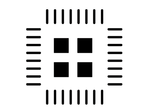
To solve these problems, solder paste is usually deposited in several small square or circular areas for IC plates with an area larger than approximately 2 mm square. Dividing the solder paste into smaller areas makes it easier for the volatile components of the flux to escape the solder paste without displacing the solder.
The solder die in the QFN package has four small openings for depositing solder paste on the central IC plate.
SOT-23 and SOIC packages
Standard lead packages (such as SOIC and SOT-23 packages) are commonly used in low power motor drivers.
In order to improve the power consumption of the lead package, the structure of "Flip Chip Lead Frame" is adopted. Without the use of bonding wires, copper bumps and solders are used to bond the chip to metal leads, through which heat can be transferred from the chip to the PCB.
Flip chip lead frame structure is helpful to improve the power consumption of lead package.
Thermal performance can be optimized by connecting large copper areas to leads that carry large currents. On the motor driver IC, the power supply, ground, and output pins are normally connected to the copper area.
The following figure shows a typical PCB layout for a "Flip Chip Lead Frame" SOIC package. Pin 2 is the device power pin. Note that the copper region is located near the top layer of the device, and several hot through holes connect this region to the copper layer on the back of the PCB. Pin 4 is the ground pin and is connected to the ground copper clad area of the surface layer. Pin 3 (device output) is also routed to the larger copper area.
Flip chip SOIC PCB layout
Please note that there is no hot air pad on the SMT plate; They are firmly connected to the copper region. This is essential for achieving good thermal properties.
QFN and TSSOP encapsulation
The TSSOP is packaged as a rectangle and uses two rows of pins. TSSOP packages for motor driver ICs usually have a large exposed plate at the bottom of the package to remove heat from the device.
TSSOP packages usually have a large exposed plate at the bottom for heat removal.
The QFN package is a leadless package with a plate around the outer edge of the device and a larger plate in the center of the bottom of the device. This larger plate is used to absorb heat from the chip.
To remove heat from these packages, the exposed plates must be well soldered. The exposed plate is usually ground potential, so it can be connected to the PCB ground layer.
Ideally, the heat through holes are located directly in the plate area. In the TSSOP package example, an 18-hole array with a drill diameter of 0.38 mm was used. The calculated thermal resistance of the through-hole array is approximately 7.7°C/W.
An 18 - hot - through - hole TSSOP encapsulated PCB layout was used
Typically, these hot through holes are drilled with a hole diameter of 0.4 mm or less to prevent tin infiltration. If the SMT process requires the use of a smaller aperture, the number of holes should be increased to keep the overall thermal resistance as low as possible.
In addition to the through-holes located in the plate area, the external area of the IC body is also provided with hot through-holes. In TSSOP packages, the copper region can be extended beyond the end of the package, providing another way for heat in the device to pass through the copper layer on top.
The panels around the edges of the QFN device package avoid using a copper layer on top to absorb heat. Heat through holes must be used to disperse heat to the inner layer or to the bottom of the PCB.
A 9-hot-through QFN encapsulated PCB layout is used
The PCB layout in the figure shows a small QFN (4 × 4 mm) device. In the exposed plate area, only nine heat through holes are accommodated. Therefore, the thermal performance of the PCB is not as good as the TSSOP package.
Flip chip QFN package
Flip Chip QFN (FCQFN) packages are similar to conventional QFN packages, except that the chip is connected directly to the board at the bottom of the device in a flip way, rather than using a bonding wire to connect to the package board. These panels can be placed on the opposite side of the heating power devices on the chip, so they are usually arranged in long strips rather than small plates.
These packages are mounted on the surface of the chip using multiple rows of copper bumps bonded to the lead frame.
The FCQFN package uses multiple rows of copper bumps on the surface of the chip bonded to the lead frame
A small through hole can be placed in the plate area, similar to a regular QFN package. On multilayer plates with power supply and grounding strata, through holes connect these plates directly to the layers. In other cases, the copper area must be directly connected to the plate in order to draw heat from the IC into the larger copper area.
The device below has a longer power supply and connector floor, and three outlets. Note that the package is only 4 x 4 mm in size.
FCQFN encapsulates the PCB layout of the IC
The copper area on the left side of the device is the power input port. This large copper area is directly connected to the two power plates of the device.
Three output plates are connected to the copper region on the right side of the device. Note that the copper area expands as much as possible after exiting the board. This is sufficient to transfer heat from the plate to the ambient air.
Also, note the rows of small through holes in the two plates on the right side of the device. These boards are grounded and a solid grounding layer is placed on the back side of the PCB. The diameter of these through holes is 0.46 mm and the diameter of the drill holes is 0.25 mm. The through-hole is small enough to fit within the plate area.
To sum up, careful PCB layout is required in order to implement a successful PCB design using a motor driver IC.
Source: Internet
DIY adjustable speed DC motor fan
1. Project introduction
I participated in the activities of ST development board and UFUN development board organized by Bread Board and learned a lot of new knowledge. Later, I wanted to make some small experiments into a small board. The main hardware function is to use STM32 to collect encoder or receive infrared data to adjust the speed of DC motor, monitor the corresponding relationship between speed and current in real time, and output the printed message to PC display through USB to serial port chip.
2. Hardware design
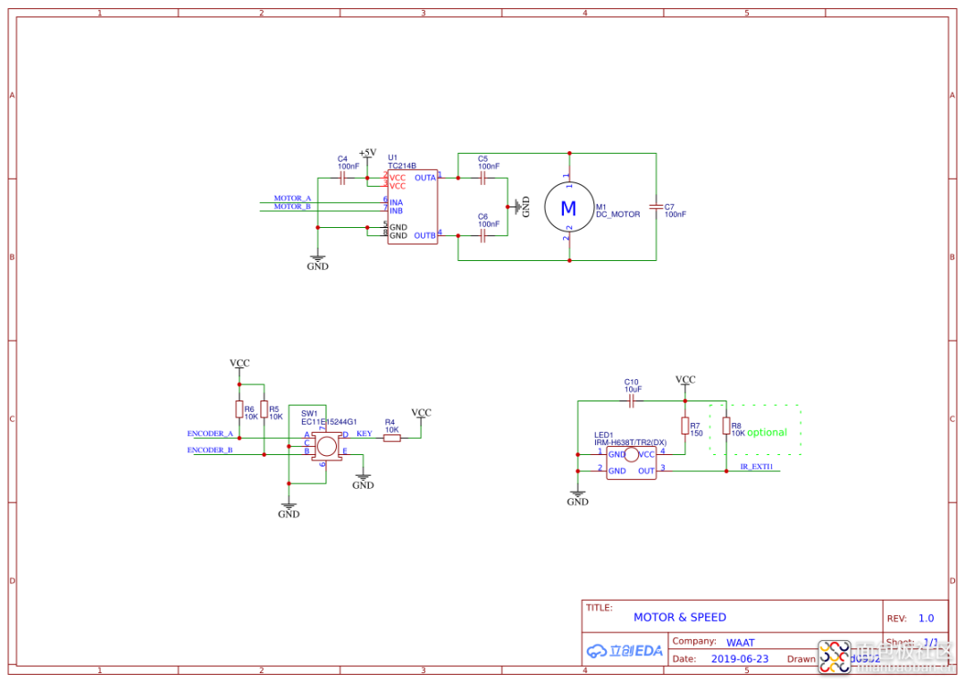
2.1. Schematic diagram design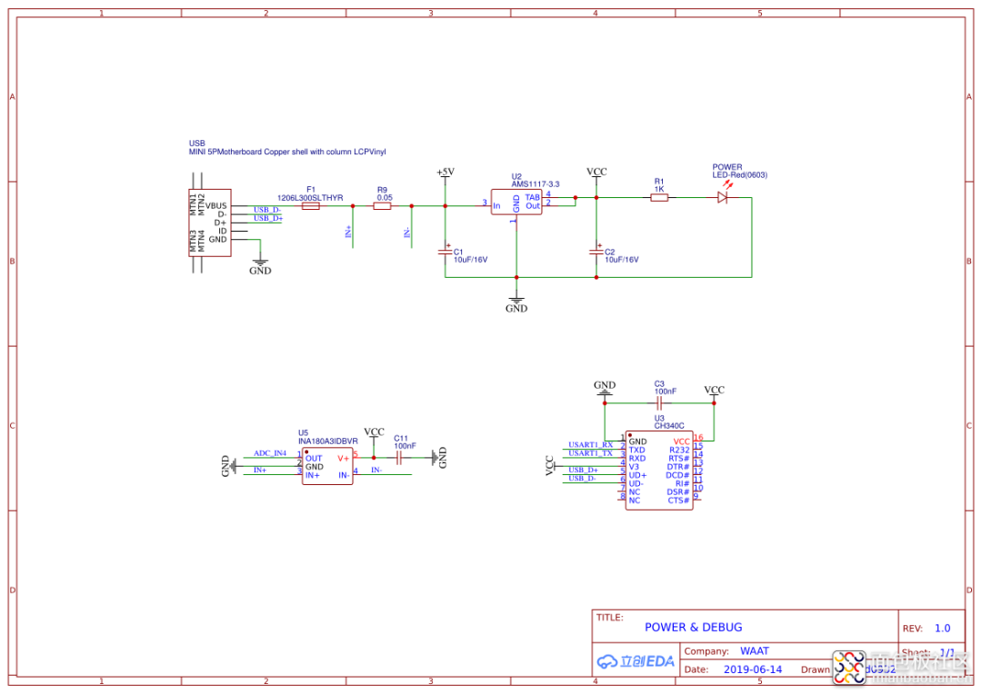
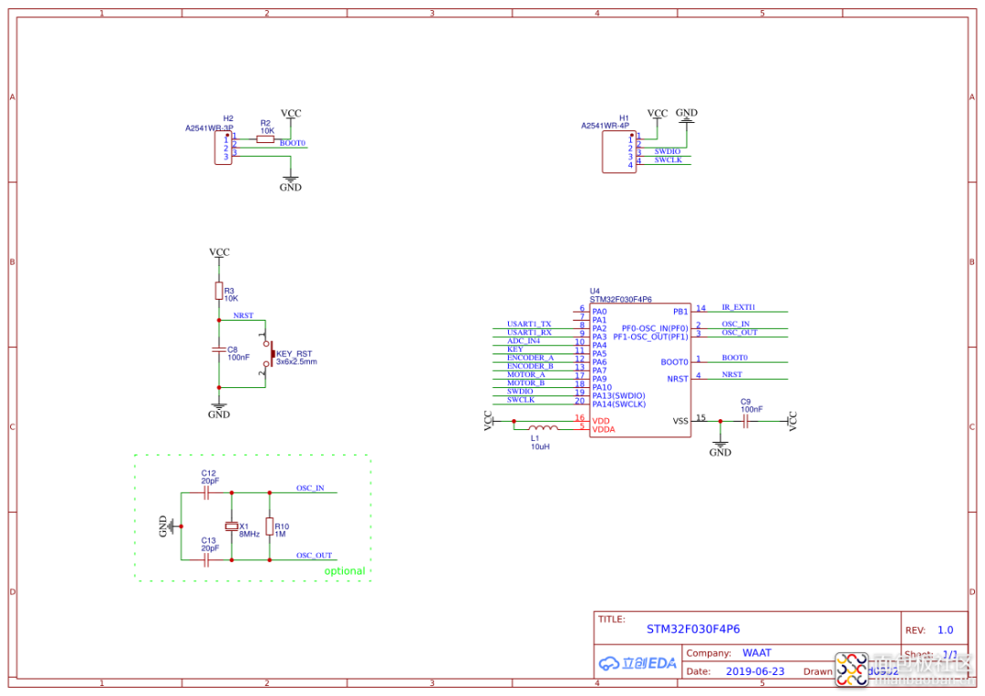
2.2. PCB design
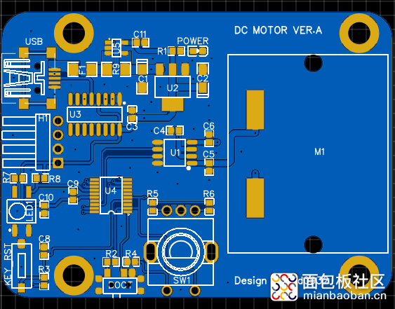
3. Welding debugging of return plate
When debugging the hardware, the output pin of the infrared receiver head is abnormal, and there is abnormal waveform output. The reason for the inspection is that the serial resistance of R7 is 10K at the beginning, which is too large. The data manual suggests that it is about 100~200R, so the infrared reception will be normal after it is changed to 150R.
4. STM32CubeMX Settings
After using STM32Cubemx to automatically generate the Keil project of MDK 5 version, directly open the project and configure the debugging tool into J-Link, SWD mode. No matter how you operate, STM32 chip cannot be recognized, schematic diagram and welding can not find any problems, and it is about to crash. Create a Keil project manually and configure it step by step. The chip can be correctly identified and downloaded. This problem also had not encountered before, do not know to have a netizen to have such experience, know is how to return a responsibility...
A big wave diagram gives you a real understanding of the motor
Electric machine is an electromagnetic mechanical device that converts electrical energy and mechanical energy into each other. The motor generally has two forms of application: the first is to convert mechanical energy into electrical energy, called a generator; The second is to convert electrical energy into mechanical energy, which is called an electric motor.
The operating principle of the motor is based on the law of electromagnetic induction and the law of electromagnetic force. When the motor carries on the energy conversion, it should have two parts that can make the relative movement: the part that establishes the exciting magnetic field, the part that induces the electromotive force and flows through the working current to be induced. Of these two parts, the stationary one is called the stator and the rotating one is called the rotor. There is an air gap between stator and rotor for rotor rotation.
Electromagnetic torque is produced by the interaction between the excited magnetic field in the air gap and the magnetic field created by the current in the part being induced. Through the action of electromagnetic torque, the generator absorbs mechanical power from the mechanical system, and the motor outputs mechanical power to the mechanical system. The above two magnetic fields are set up in different ways, forming different kinds of motors.
1, according to the type of working power supply
2. Divided by structure and working principle
3. Divided by startup and operation mode
4, according to the structure of the rotor
